Previously. Choosing a huge radiator: Phase Change Practicalities
Having pretty much decided and engineered how the cooling will work I moved on towards designing a case that would appeal to me artistically and also feature wise.
Additionally to all the usual stuff like mainboard and power supply mounting it should also have at least six 5.52 inch drive bays and at least space for six 3.5 inch internal data drives.
Also, most importantly. This would be a passive cooling case. So no mounting points for fans and the most possible "airflow windows" to allow for unhindered flow of air trough the case.
So pulled out pen and paper and scribbled up some very basic geometric shapes I would find fun but could also work realistically ... I found the same sided Pentagon a great, although understandably, underused shape.
In the end I settled with this: At the front a single point that further back transforms into a fully fletched pentagon with a side up, at the end an angled rectangle. In between all this: Connecting lines, what I would call "interfaces" that pretty much fill up the rest of the surfaces.
This would give the case a triangular base and rectangular top. I sacrificed stability as I needed space at the top for the huge radiator. I wanted the radiator to be inside the case of course.
I knew I would set myself up for a challenge.
Now that the shape was decided I started up my CAD software to plan this out ...
What manufacturing method to use? In a previous project I quite enjoyed designing with laser cut and machine bent sheet metal, I found it a quite elegant way of construction. I also like bolts and nuts. I did decide on the materials later on ... but it turned out to be steel sheet with a protective galvanized zinc layer, like in the previous project. I liked the aesthetic and steel was a better trade off in my opinion. I needed the increased strength and stiffness as I had a lot of quite long unsupported pieces in there.
For the "airflow windows" I used 6 x 6,7 mm Hexagon perforated metal plate. They offer the best compromise between dust protection and airflow with a stunning 80.2% free cross section.
Anyway. I started off by measuring the radiator I thankfully already ordered. This gave me the minimum size of the whole thing as the with was in direct correlation with the height trough the pentagon at the front.
I did the first main part. The backbone. A U shaped piece including the base, the back and the top of the case.
Next was the pentagon front pentagon witch would connect with the backbone and create a box when viewed from the side. The front pentagon would also hold the 5.25 inch drive bays. I had the choice to either leave the front pentagon flat or ... doing something more elaborate.
So of course I went the hard route. Creating two mirrored parts. Each with six consecutive bends which angles would need to be bend to below degree accuracy for it to connect up correctly.
This was pretty much what was holding up the rest of the case. During design I would often come back to these parts to add holes and mounting points, etc. for the many many other parts.
Following that were the mainboard tray. Researching all the measures needed like, whole distances, spacing, positioning took the most time on that part. Especially as there were like three separate standards for each and not a single document. I even had to calculate some measures as they weren't measured from the same reference point.
As the back of the case was angled I had to add some parts to connects the mainboard tray ... oh and the tray is completely decoupled from the rest of the case ... for some reason. I probably thought it was fun to do.
Doors, connectors for the radiator and manifolds, drive holders. All with very obscure shapes and surfaces.
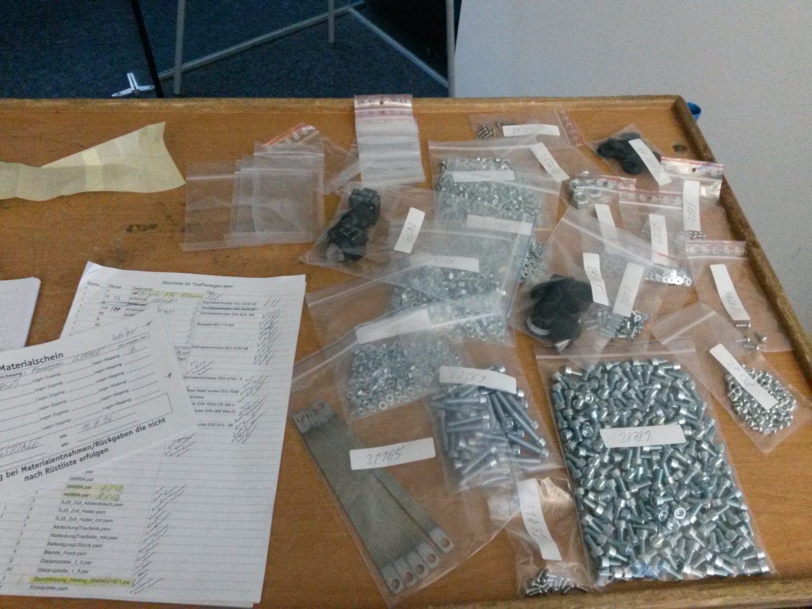
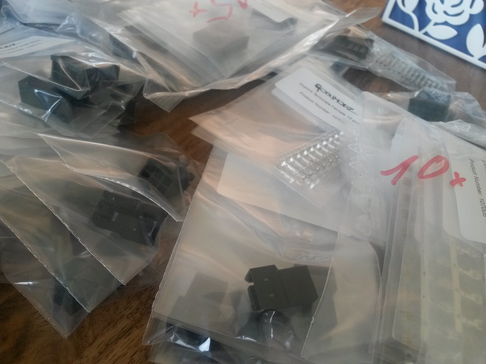
Additionally to designing the sheet metal parts there was nearly the same amount of time dedicated to finding and deciding on buy in parts like door hinges, rubber decouplers, screws, etc.. There's huge detail I could go into every detail of the project. If you want that detail just hit me up with an email or something.
At the front I wanted a flower like artistic door. Five triangular sheets that would be actuatable to open and close. Quite some time was put into the feature and making it work just in the CAD was a nightmare ... although most parts were. These parts needed sheet metal risers because of how the geometry turned out ...
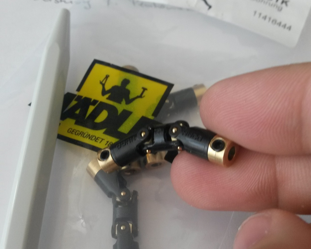
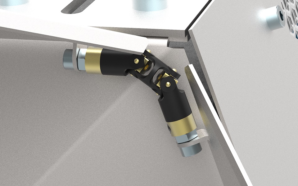
The idea was to have one electric linear actuator to move the up most panel and have double universal joints at the bottom of each panel to transfer that rotation.
Spoiler ... it didn't work out. The forces were just too much, the joints were to minuscule, much to big lever action going on and the parts just wanted to go somewhere else than turn ... I kept them nevertheless and just fixed the four unmovable to an acceptable position.
In the end I had constructed 22 types of metal sheets for a total of 60 sheets used. After a last check based on the 3D model I created the needed drawings for the supplier.
Ordering most buy in parts was quite easy, as I payed attention to choose retailers with uncomplicated ordering. Some of the ordering I did trough my employer.
For the sheet metal parts I wanted to work with the guys who did the parts for my previous metal project. They did an amazing job. I myself can't believe how they did most of the bends. Without the expertise of them this project could have never been realized. There are limits to metal bending but with the right variety of techniques even the mots mindbending shapes can be manufactured.
Next: Painting and assembling The Pentagon
Here some nice renders:
View post on imgur.com
View post on imgur.com
Next: Painting and assembling The Pentagon